Dana Hinaman is stormwater consultant for Contech Engineered Solutions. Hinaman can be reached at [email protected] or 513.314.4781.
The I-70/71 Columbus Crossroads project is a multi-phase roadway improvement conducted by the Ohio Department of Transportation (ODOT). Many factors contributed to the need for this multi-phase project. More than 900 freeway crashes were reported per year due to congestion in and out of downtown and unsafe ramps, so the removal of these ramps and enhanced freeway crossings were needed.
With these added safety features, new urban avenues would become complete streets with safe pedestrian and bike accommodations, and overall water quality improvements would be made to increase the quality of the water entering the Scioto River. With the increase in rainfall intensity over the years, the need for runoff improvements were critical for this project. In addition, with the increase of critical storms, trash capture also was of importance to prevent debris from exiting the highway. This would ensure the safety of the surrounding waterways within the greater Columbus area.
Project Phases
Phase 2B focused on storm sewer improvements in the I-70/71 corridor. The total funding cost for Phase 2B was $9 million, and its scope encompassed 0.24 miles of new storm sewer. Storm water no longer would be connected to the city’s combined sewer system, and the separated freeway storm water then could pass through a settlement tank to remove grit and debris from the roadway. With this new storm sewer, relocation of the waterline and sanitary sewer was needed, as well as the installation of water quality best management practices (BMP). The water quality BMP had to take into consideration loading from a future retaining wall, as well as a minimum floatation safety factor of 1.25 for buoyancy. This factor of safety would be taken into account for any empty structure and groundwater at surface elevation. Total water quality flow was 75 cu ft per second with 38.05 cu ft per second coming from Phases 1 to 4 plus part of Phase 5, 0.14 cu ft per second from Phase 2B, and finally 36.81 cu ft per second for future projects and phases.
Using MTDs
Per ODOT requirements, any manufactured treatment device (MTD) used for water quality purposes had to be approved per SS995 testing criteria. This testing targets the OK110 particle size distribution. The system had to treat the 75 cu ft per second of water, and had to work within either a 15-ft wide by 36-ft long, or 30-ft wide by 36-ft long footprint. There were no pre-approvals by ODOT or the Engineer of Record (EOR). Manufacturers had to work with the awarded contractor on a solution that would fit within the “box” provided by ODOT. Five alternative designs were completed by Contech Engineered Solutions and provided to the EOR and ODOT. Contech proposed either the Vortechs hydrodynamic separator or the Continuous Deflection Separation (CDS) hydrodynamic separator. Each of these units had SS995 testing and were on ODOT Qualified Products List.
Initially, ODOT wanted a one-structure system. A Vortechs system with a 36-ft swirl chamber inside a precast CON/Span structure was proposed, but was rejected due to layout constraints and price. Next, the CDS unit was considered as a solution. The CDS unit utilizes a combination of swirl concentration and indirect screening to separate debris, sediment and hydrocarbons entering from the freeway runoff, as well as addressing trash capture. Five different configurations were put together utilizing the CDS unit.
It was determined that four 10-ft-diameter CDS units would be needed to treat the required 75-cu-ft-per-second flow. These units fell outside of the standard Qualified Products List sizing for a Type 1, 2, 3 or 4 unit. A Type 1 unit treats up to 1 cu ft per second, Type 2 treats up to 2 cu ft per second, Type 3 treats up to 3 cu ft per second and a Type 4 unit treats up to 6 cu ft per second. Special consideration and approval was given for utilizing the 10-ft units due to the large water quality flow.
The first layout included a vault on the upstream end to collect the water, then pipe distributed storm water into the four CDS units. These units then discharged to two 96-in. manholes, which connected together at a junction structure. It was then later modified into collection vault on the downstream end, replacing the 96-in. collection manholes. Once the layout of an upstream vault, four CDS units, and a downstream vault was selected, four iterations of the design were done to fit the system in the required footprint ODOT provided. The first iteration, which was the most compact system, was larger than the required footprint at 30-ft wide by 36-ft long. This design was rejected as the waterline went directly through the system. After four more iterations, Option E was selected. This system was selected after conversations with ODOT, as any configuration of the system could not stay within the originally proposed footprint. The final footprint was 30-ft wide by 52-ft-and-6-in. long. This resulted in all four CDS units being in linear sequence, again with the upstream and downstream collection vaults.
Installation
Installation of the CDS units was done over the course of two days in November 2016. Each of the CDS units was 21-ft deep, and the heaviest pick weight on each unit was 43,500 lb. Each collection vault was 6-ft wide by 22-ft long. This resulted in a vault pick weight of 59,500 lb. Due to the size of the units, it was required they be delivered in sections and assembled on site. Shoring was needed to install at the required depth, so a crane lowered each CDS cylinder connection piece into place on site. The first unit’s bottom slab was placed, then the following units’ bottom slabs were placed in a sequential order. After the first slab was placed, the first unit’s concrete connecting cylinder extension then was placed on the bottom slab.
There were a total of three connection cylinder pieces for each unit in addition to the base slab. Each piece was connected with butyl rope. Once the cylinder extensions were placed, a Contech field installation team member installed the internal components of each CDS unit to ensure proper installation and functionality. The indirect screens for the CDS units were 5.6-ft by 7.8-ft and 5.6-ft by 5.3-ft. The fiberglass internals were more than 6-ft high. Once the internals were installed, the top slab of each unit was placed, and once each unit was set with the internals installed, they then were connected to the vaults to complete the system. Risers brought the system up to the finished grade. Frame and covers were consistent with the city of Columbus' requirements.
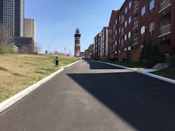
After installation of the CDS units and collection vaults was completed, the area was brought to finished grade and paved with asphalt. After total project construction was complete, post development photos were taken of the site. Overall, the contractor and ODOT were happy with the outcome of the project. Due to the specific site constraints, the solution was outside of the normal ODOT project scope. Being able to work closely and have open communication with ODOT, the EOR and contractor improved the efficiency of the design, as well as resulted in a speedy installation.


